PCF Custom Command Configuration File (.xml)
Note
This file defines custom PCF commands that can be used in Pin Constraints File (.xml). It specifies how user-facing commands are translated into FPGA configuration bits. See details in pcf2bitstream_setting.
PCF is the unified file used by users to manipulate FPGA I/Os. Custom commands in PCF provide a simple and straightforward way for users to configure FPGA I/Os into their desired operating modes without understanding the underlying bitstream-level details. The custom command configuration file encapsulates the mapping from these high-level commands to the corresponding bit-level configuration details.
The following diagram illustrates how the PCF custom commands configure FPGA modules through the management stack and special I/O interface:
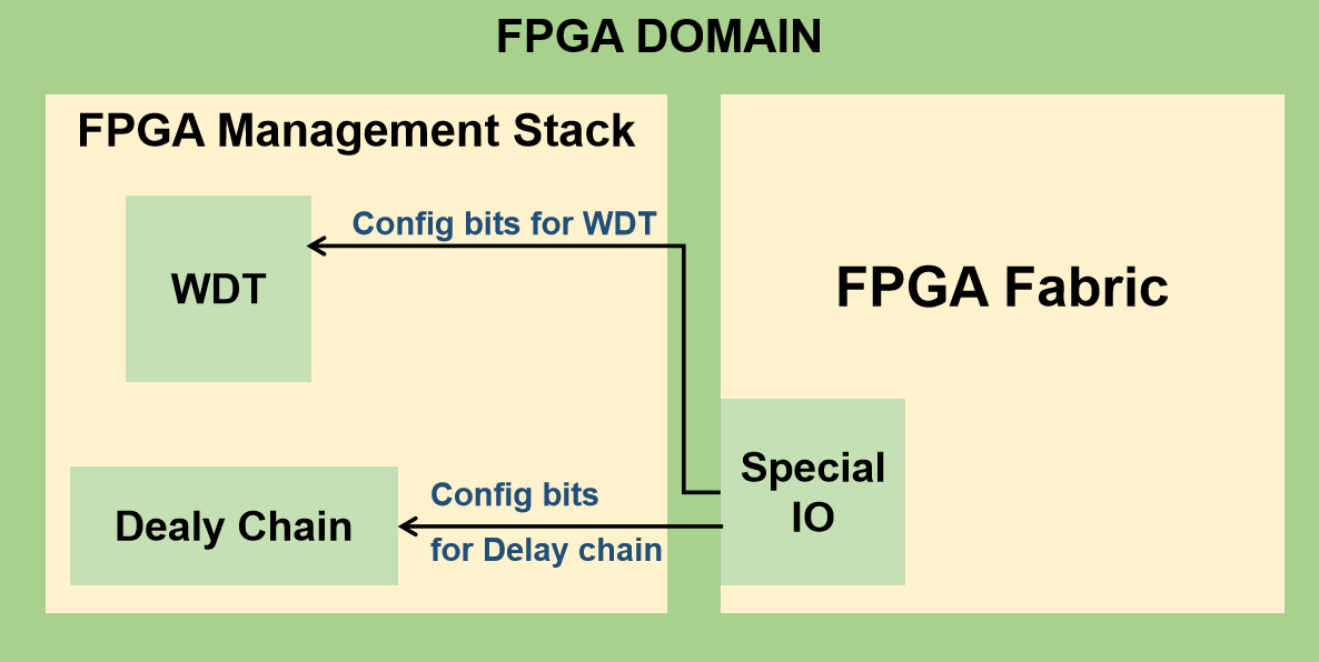
Fig. 84 An example of FPGA Domain with Management Stack and Fabric
As shown in the figure Fig. 84
FPGA Management Stack contains functional modules such as the Delay Chain and WDT. Each module receives configuration bits from the PCF parser based on the user-specified commands.
Special I/O interfaces transfer configuration bits from the management stack to the corresponding hardware blocks in the FPGA Fabric.
Users interact only with high-level commands in the PCF file. For example, to configure a programmable delay chain in an I/O, the user simply specifies:
set_delay_chain -pad pad_io[0] -delay 0.2ns
where set_delay_chain is defined in the following PCF custom command configuration file:
<pcf_config>
  <command name="set_delay_chain" type="delay_chain">
    <option name="pad" type="pin"/>
    <pb_type name="gp_inpad.inpad"/>
    <option name="delay" type="mode" offset="0">
      <mode name="0.1ns">00001</mode>
      <mode name="0.2ns">00010</mode>
      <mode name="0.3ns">00100</mode>
    </option>
  </command>

  <command name="set_watch_dog" type="peripheral">
    <option name="pad" type="pin"/>
    <pb_type name="gp_outpad.outpad"/>
    <option name="mode" type="decimal" num_bits="3" max="6" little_endian="false" offset="0">
      <segment range = "[0:0]" offset = "2"/>
      <segment range = "[1:2]" offset = "0"/>
    </option>
  </command>
</pcf_config>
The parser will map the mode name 0.2ns to the corresponding bit pattern 00010 and programs the Delay Chain via the Special I/O.
General Settings
The following syntax are applicable to the XML definition under the root node pcf_config
- command name="<string>"
The name of the custom command as used in the PCF file.
- type="<string>"
The category of the custom command used internally by the parser.
- option name="<string>" type="<pin|mode|decimal>" [additional attributes]
Defines a configurable parameter for the custom command.
pin: Specifies an I/O pad. Users provide a valid pad name from the pin table Pin Table File (.csv). The parser validates the name.
mode: Users select a predefined mode by name (e.g., NORMAL, LOW_SPEED, HIGH_SPEED). Each mode has an explicit bit pattern defined in the configuration file.
decimal: Users specify a numeric value (for example, a delay parameter). The parser converts this value into the corresponding bit pattern or mode bits.
Note
The following options are required when the type is set to
decimal:num_bits: Number of bits used to encode the numeric value.
max: Maximum allowable value in decimal format. This value must be representable by
num_bits.little_endian: Specifies the bit ordering used during encoding.
offset: Bit offset applied when overwriting the target bitstream. The encoded value is written starting at this bit position, and occupies
num_bitsconsecutive bits.
Note
Example
If
num_bitsis set to 4, the maximum representable value is 15 (binary1111). Therefore,maxshould not exceed 15.If
offsetis set to 8, the 4-bit encoded value overwrites bit positions[8 : 11]in the target bitstream (inclusive).When a user provides a value greater than
max, the parser reports an error and aborts bitstream generation, preventing bits overflow.Note
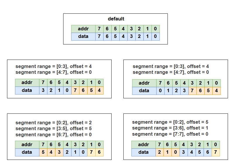
The
segmentoption is optional when the type is set todecimal. It is used to split the mode and rearrange the mode bits:range: The range of mode bits to be extracted. The range must be valid within
num_bits. For example, ifnum_bits = 16, the acceptable range is[0:15].offset: The offset index applied to the resulting data. The offset must indicate a valid starting index within
num_bitsand a valid ending index within the total width of the specified range. For example, in the following context, when the input data is111100, the resulting data will be100111.<option name="delay" type="decimal" num_bits="6" max="32" little_endian="false" offset="0"> <segment range="[0:1]" offset="4"/> <segment range="[2:2]" offset="3"/> <segment range="[3:5]" offset="0"/> </option>
The following diagram illustrates how to rearrange mode bits with the segment option:
- pb_type name="<string>"
Specify the programmable block associated with this command, whose configuration bits will be modified.
Note
Please provide the full path of the pb_type in the VPR hierarchy. It must be a pb_type in a mappable mode which is not disabled during packing.
- mode name="<string>" value="<bit pattern>"
Used only under a mode-type option. Defines the mapping between a mode name and its explicit bit pattern.