Bind circuit modules to VPR architecture
Each defined circuit model should be linked to an FPGA module defined in the original part of architecture descriptions. It helps FPGA-circuit creating the circuit netlists for logic/routing blocks. Since the original part lacks such support, we create a few XML properties to link to Circuit models.
Switch Blocks
Original VPR architecture description contains an XML node called switchlist under which all the multiplexers of switch blocks are described. To link a defined circuit model to a multiplexer in the switch blocks, a new XML property circuit_model_name should be added to the descriptions.
Here is an example:
<switch_block>
  <switch type="mux" name="<string>" circuit_model_name="<string>"/>
</switch_block>
circuit_model_name="<string>"should match a circuit model whose type ismuxdefined in Circuit Library.
Connection Blocks
To link the defined circuit model of the multiplexer to the Connection Blocks, a circuit_model_name should be annotated to the definition of Connection Blocks switches.
Here is the example:
<connection_block>
  <switch type="ipin_cblock" name="<string>" circuit_model_name="<string>"/>
</connection_block>
circuit_model_name="<string>"should match a circuit model whose type ismuxdefined in Circuit Library.
Channel Wire Segments
Similar to the Switch Boxes and Connection Blocks, the channel wire segments in the original architecture descriptions can be adapted to provide a link to the defined circuit model.
<segmentlist>
  <segment name="<string>" circuit_model_name="<string>"/>
</segmentlist>
circuit_model_name="<string>"should match a circuit model whose type ischan_wiredefined in Circuit Library.
Physical Tile Annotation
Original VPR architecture description contains <tile> XML nodes to define physical tile pins.
OpenFPGA allows users to define pin/port of physical tiles as global ports.
Here is an example:
<tile_annotations>
  <physical_equivalent_site tile="<string>" subtile="<string>" site="<string>"/>
  <merge_subtile_ports tile="<string>" port="<string>"/>
  <global_port name="<string>" is_clock="<bool>" clock_arch_tree_name="<string>" is_reset="<bool>" is_set="<bool>" default_val="<int>">
    <tile name="<string>" port="<string>" x="<int>" y="<int>"/>
    ...
  </global_port>
</tile_annotations>
For physical equivalent site,
Note
If there is only 1 equivalent site for a subtile, it will be automatically inferred as the physical site. If there are more than 1 equivalent sites for a subtile, a physical site must be defined explicitedly.
tile="<string>"is the name of tile, that is defined in VPR architecturesub_tile="<string>"is the name of sub tile, that is defined in VPR architecturesite="<string>"is the name of an equivalent site defined under the subtile, that is defined in VPR architecture
Fig. 71 illustrates an example where two pb_type tree is considered as equivalent.
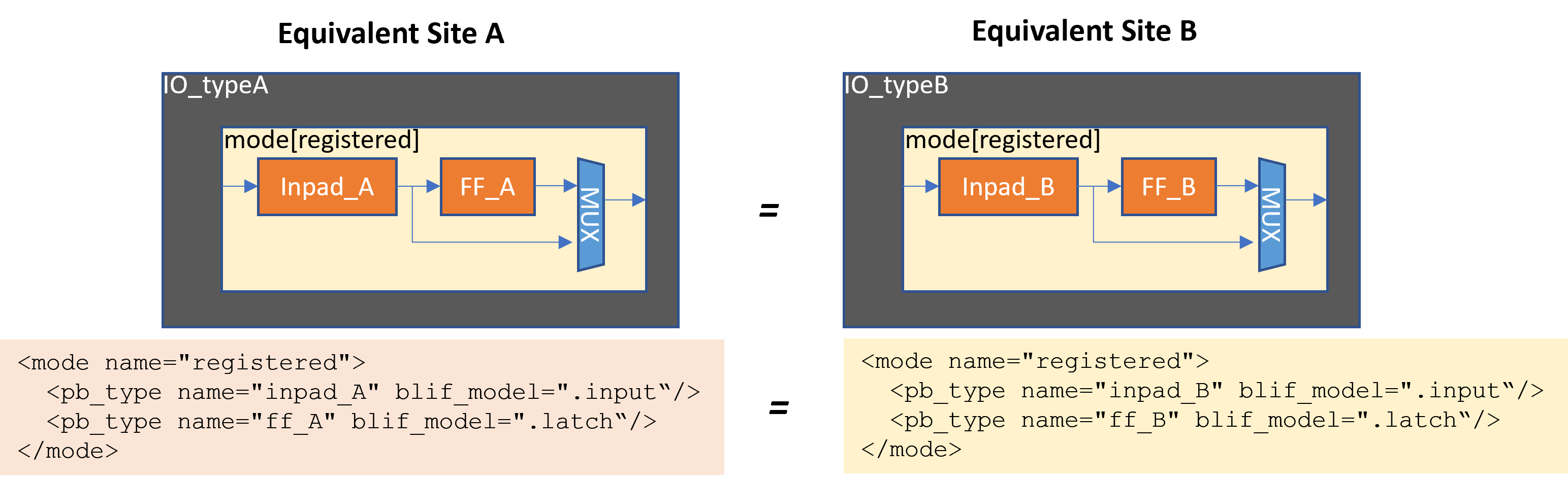
Fig. 71 An illustrative example how OpenFPGA identifies two pb_type tree are equivalent
For subtile port merge support (see an illustrative example in Fig. 72):
tile="<string>"is the name of tile, that is defined in VPR architectureport="<string>"is the name of a port of the tile, that is defined in VPR architecture
Warning
This is an option for power users. Suggest to enable for those global input ports, such as clock and reset, whose Fc is set to 0 in VPR architecture!!!
Note
When defined, the given port of all the subtiles of a tile will be merged into one port. For example, a tile consists of 8 subtile A and 6 subtile B and all the subtiles have a port clk, in the FPGA fabric, all the clk of the subtiles A and B will be wired to a common port clk at tile level.
Note
Note that when a dedicated clock network is defined, the size of the global port will follow the global_port defined in the clock network description file (See details in Clock Network (.xml))
Note
When merged, the port will have a default side of TOP and index of 0 on all the attributes, such as width, height etc.
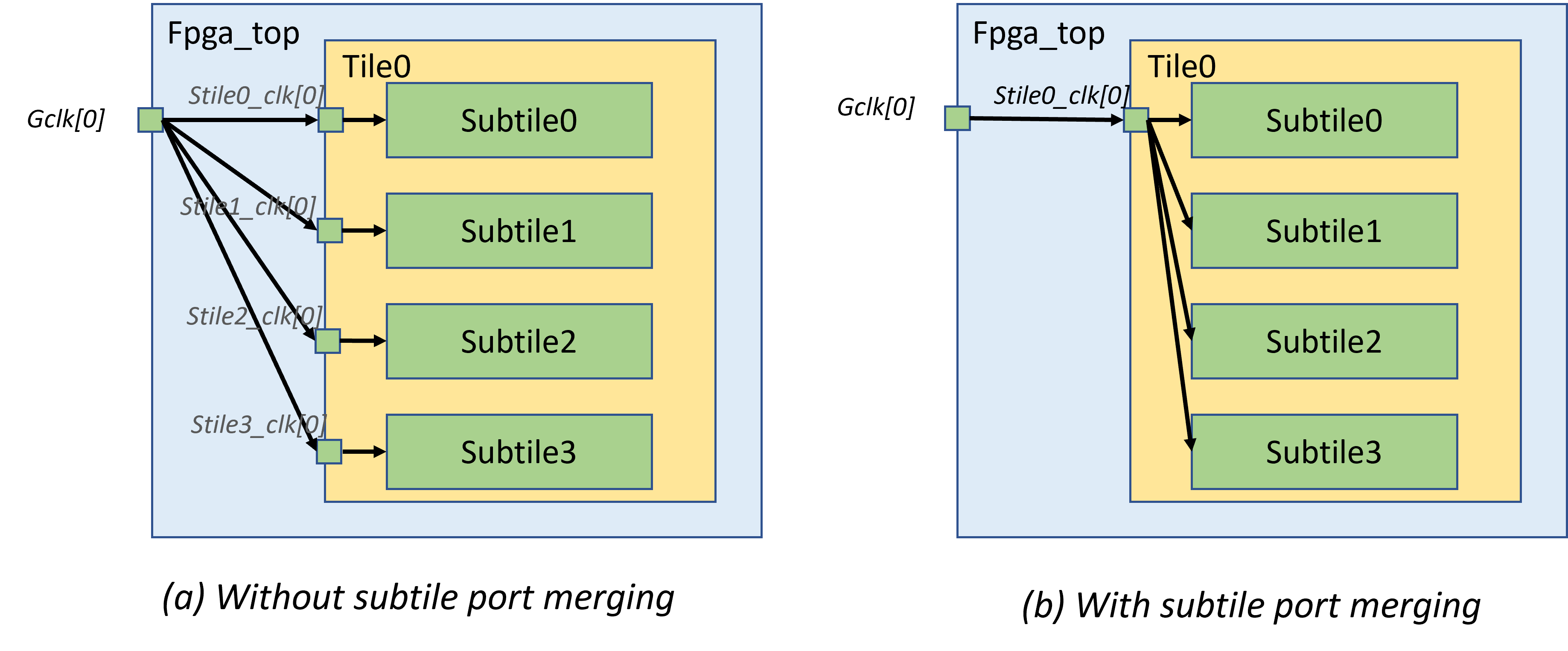
Fig. 72 Difference in netlists with and without subtile port merging
For global port support:
Note
If you choose to route the global signal through the global port network, you should set the --clock_modeling ideal when running VPR. In such case, VPR will still reserve an I/O for the global signals without any routing traces. If you are minimize the I/O for your FPGA, please take the number of reserved I/Os into account!
name="<string>"is the port name to appear in the top-level FPGA fabric.is_clock="<bool>"define if the global port is a clock port at the top-level FPGA fabric. An operating clock port will be driven by proper signals in auto-generated testbenches.clock_arch_tree_name="<string>"defines the name of the programmable clock network, which the global port will drive. The name of the programmable clock network must be a valid name (See details in Clock Network (.xml))
Note
clock_arch_tree_name is applicable to clock, reset and set signals.
is_reset="<bool>"define if the global port is a reset port at the top-level FPGA fabric. An operating reset port will be driven by proper signals in testbenches.is_set="<bool>"define if the global port is a set port at the top-level FPGA fabric. An operating set port will be driven by proper signals in testbenches.
Note
A port can only be defined as clock or set or reset.
Note
All the global port from a physical tile port is only used in operating phase. Any ports for programmable use are not allowed!
default_val="<int>"define if the default value for the global port when initialized in testbenches. Valid values are either0or1. For example, the default value of an active-high reset pin is0, while an active-low reset pin is1.
Note
A global port could be connected from different tiles by defining multiple <tile> lines under a global port!!!
- <tile name="<string>" port="<string>" x="<int>" y="<int>"/>
name="<string>"is the name of a physical tile, e.g.,name="clb".port="<string>"is the port name of a physical tile, e.g.,port="clk[0:3]".x="<int>"is the x coordinate of a physical tile, e.g.,x="1". If the x coordinate is set to-1, it means all the valid x coordinates of the selected physical tile in the FPGA device will be considered.y="<int>"is the y coordinate of a physical tile, e.g.,y="1". If the y coordinate is set to-1, it means all the valid y coordinates of the selected physical tile in the FPGA device will be considered.
Note
The port of physical tile must be a valid port of the physical definition in VPR architecture! If you define a multi-bit port, it must be explicitly defined in the port, e.g., clk[0:3], which must be in the range of the port definition in physical tiles of VPR architecture files!!!
Note
The linked port of physical tile must meet the following requirements:
If the
global_portis set as clock throughis_clock="true", the port of the physical tile must also be a clock port.If not a clock, the port of the physical tile must be defined as non-clock global
The port of the physical tile should have zero connectivity (
Fc=0) in VPR architecture
A more illustrative example:
Fig. 73 illustrates the difference between the global ports defined through circuit_model and tile_annotation.
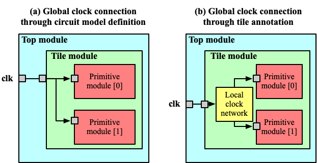
Fig. 73 Difference between global port definition through circuit model and tile annotation
When a global port, e.g., clk, is defined in circuit_model using the following code:
<circuit_model>
  <port name="clk" is_global="true" is_clock="true"/>
</circuit_model>
Dedicated feedthrough wires will be created across all the modules from top-level to primitive.
When a global port, e.g., clk, is defined in tile_annotation using the following code:
<tile_annotations>
  <global_port name="clk" is_clock="true">
    <tile name="clb" port="clk"/>
  </global_port>
</tile_annotations>
Note that a global port can also be defined to drive only a partial bit of a port of a physical tile.
<tile_annotations>
  <global_port name="clk" is_clock="true">
    <tile name="clb" port="clk[3:3]"/>
  </global_port>
</tile_annotations>
Clock port clk of each clb tile will be connected to a common clock port of the top module, while local clock network is customizable through VPR’s architecture description language. For instance, the local clock network can be a programmable clock network.
Primitive Blocks inside Multi-mode Configurable Logic Blocks
The architecture description employs a hierarchy of pb_types to depict the sub-modules and complex interconnections inside logic blocks. Each leaf node and interconnection in the pb_type hierarchy should be linked to a circuit model.
Each primitive block, i.e., the leaf pb_types, should be linked to a valid circuit model, using the XML syntax circuit_model_name.
The circuit_model_name should match the given name of a circuit_model defined by users.
<pb_type_annotations>
  <!-- physical pb_type binding in complex block IO -->
  <pb_type name="io" physical_mode_name="physical"/>
  <pb_type name="io[physical].iopad" circuit_model_name="iopad" mode_bits="1"/>
  <pb_type name="io[inpad].inpad" physical_pb_type_name="io[physical].iopad" mode_bits="1"/>
  <pb_type name="io[outpad].outpad" physical_pb_type_name="io[physical].iopad" mode_bits="0"/>
  <!-- End physical pb_type binding in complex block IO -->

  <!-- physical pb_type binding in complex block CLB -->
  <!-- physical mode will be the default mode if not specified -->
  <pb_type name="clb">
    <!-- Binding interconnect to circuit models as their physical implementation, if not defined, we use the default model -->
    <interconnect name="crossbar" circuit_model_name="mux_2level"/>
  </pb_type>
  <pb_type name="clb.fle" physical_mode_name="physical"/>
  <pb_type name="clb.fle[physical].fabric.frac_logic.frac_lut6" circuit_model_name="frac_lut6" mode_bits="0"/>
  <pb_type name="clb.fle[physical].fabric.ff" circuit_model_name="static_dff"/>
  <!-- Binding operating pb_type to physical pb_type -->
  <pb_type name="clb.fle[n2_lut5].lut5inter.ble5.lut5" physical_pb_type_name="clb.fle[physical].fabric.frac_logic.frac_lut6" mode_bits="1" physical_pb_type_index_factor="0.5">
    <!-- Binding the lut5 to the first 5 inputs of fracturable lut6 -->
    <port name="in" physical_mode_port="in[0:4]"/>
    <port name="out" physical_mode_port="lut5_out" physical_mode_pin_rotate_offset="1"/>
  </pb_type>
  <pb_type name="clb.fle[n2_lut5].lut5inter.ble5.ff" physical_pb_type_name="clb.fle[physical].fabric.ff"/>
  <pb_type name="clb.fle[n1_lut6].ble6.lut6" physical_pb_type_name="clb.fle[physical].fabric.frac_logic.frac_lut6" mode_bits="0">
    <!-- Binding the lut6 to the first 6 inputs of fracturable lut6 -->
    <port name="in" physical_mode_port="in[0:5]"/>
    <port name="out" physical_mode_port="lut6_out"/>
  </pb_type>
  <pb_type name="clb.fle[n1_lut6].ble6.ff" physical_pb_type_name="clb.fle[physical].fabric.ff" physical_pb_type_index_factor="2" physical_pb_type_index_offset="0"/>
  <!-- End physical pb_type binding in complex block IO -->
</pb_type_annotations>
- <pb_type name="<string>" physical_mode_name="<string>">
Specify a physical mode for multi-mode
pb_typedefined in VPR architecture.Note
This should be applied to non-primitive
pb_type, i.e.,pb_typehave childpb_type.name="<string>"specifiy the full name of apb_typein the hierarchy of VPR architecture.physical_mode_name="<string>"Specify the name of the mode that describes the physical implementation of the configurable block. This is critical in modeling actual circuit designs and architecture of an FPGA. Typically, only onephysical_modeshould be specified for each multi-modepb_type.
Note
OpenFPGA will infer the physical mode for a single-mode pb_type defined in VPR architecture
- <pb_type name="<string>" physical_pb_type_name="<string>"
- circuit_model_name="<string>" mode_bits="<int>"
- physical_pb_type_index_factor="<float>" physical_pb_type_index_offset="<int>">
Specify the physical implementation for a primitive
pb_typein VPR architectureNote
This should be applied to primitive
pb_type, i.e.,pb_typehave no children.Note
This definition should be placed directly under the XML node
<pb_type_annotation>without any intermediate XML nodes!name="<string>"specifiy the full name of apb_typein the hierarchy of VPR architecture.physical_pb_type_name=<string>creates the link onpb_typebetween operating and physical modes. This syntax is mandatory for every primitivepb_typein an operating modepb_type. It should be a valid name of primitivepb_typein physical mode.circuit_model_name="<string>"Specify a circuit model to implement apb_typein VPR architecture. Thecircuit_model_nameis mandatory for every primitive``pb_type`` in a physical_modepb_type.mode_bits="<string>"Specify the configuration bits for thecircuit_modelwhen operating at an operating mode. The length ofmode_bitsshould match theportsize defined incircuit_model. Themode_bitsshould be derived from circuit designs while users are responsible for its correctness. FPGA-Bitstream will add themode_bitsduring bitstream generation. See details in Default Mode Bits-related Settings about the formatphysical_pb_type_index_factor="<float>"aims to align the indices forpb_typebetween operating and physical modes, especially when an operating mode contains multiplepb_type(num_pb>1) that are linked to the same physicalpb_type. Whenphysical_pb_type_nameis larger than 1, the index ofpb_typewill be multipled by the given factor.physical_pb_type_index_offset=<int>aims to align the indices forpb_typebetween operating and physical modes, especially when an operating mode contains multiplepb_type(num_pb>1) that are linked to the same physicalpb_type. Whenphysical_pb_type_nameis larger than 1, the index ofpb_typewill be shifted by the given factor.
- <interconnect name="<string>" circuit_model_name="<string>">
name="<string>"specify the name of ainterconnectin VPR architecture. Different frompb_type, hierarchical name is not required here.circuit_model_name="<string>"For the interconnection type direct, the type of the linked circuit model should be wire. For multiplexers, the type of linked circuit model should bemux. For complete, the type of the linked circuit model can be eithermuxorwire, depending on the case.
Note
A
<pb_type name="<string>">parent XML node is required for the interconnect-to-circuit bindings whose interconnects are defined under thepb_typein VPR architecture description.
- <port name="<string>" physical_mode_port="<string>"
- physical_mode_pin_initial_offset="<int>"
- physical_mode_pin_rotate_offset="<int>"/>
- physical_mode_port_rotate_offset="<int>"/>
Link a port of an operating
pb_typeto a port of a physicalpb_typename="<string>"specifiy the name of aportin VPR architecture. Different frompb_type, hierarchical name is not required here.physical_mode_pin="<string>" creates the link of ``portofpb_typebetween operating and physical modes. This syntax is mandatory for every primitivepb_typein an operating modepb_type. It should be a validportname of leafpb_typein physical mode and the port size should also match.Note
Users can define multiple ports. For example:
physical_mode_pin="a[0:1] b[2:2]". When multiple ports are used, thephysical_mode_pin_initial_offsetandphysical_mode_pin_rotate_offsetshould also be adapt. For example:physical_mode_pin_rotate_offset="1 0")physical_mode_pin_initial_offset="<int>"aims to align the pin indices forportofpb_typebetween operating and physical modes, especially when part of port of operating mode is mapped to a port in physicalpb_type. Whenphysical_mode_pin_initial_offsetis larger than zero, the pin index ofpb_type(whose index is large than 1) will be shifted by the given offset.Note
A quick example to understand the initial offset For example, an initial offset of -32 is used to map
operating pb_type
bram[0].dout[32]with a full pathmemory[dual_port].bram[0]operating pb_type
bram[0].dout[33]with a full pathmemory[dual_port].bram[0]
to
physical pb_type
bram[0].dout_a[0]with a full pathmemory[physical].bram[0]physical pb_type
bram[0].dout_a[1]with a full pathmemory[physical].bram[0]
Note
If not defined, the default value of
physical_mode_pin_initial_offsetis set to0.physical_mode_pin_rotate_offset="<int>"aims to align the pin indices forportofpb_typebetween operating and physical modes, especially when an operating mode contains multiplepb_type(num_pb>1) that are linked to the same physicalpb_type. Whenphysical_mode_pin_rotate_offsetis larger than zero, the pin index ofpb_type(whose index is large than 1) will be shifted by the given offset, each time a pin in the operating mode is binded to a pin in the physical mode.Note
A quick example to understand the rotate offset For example, a rotating offset of 9 is used to map
operating pb_type
mult_9x9[0].a[0]with a full pathmult[frac].mult_9x9[0]operating pb_type
mult_9x9[1].a[1]with a full pathmult[frac].mult_9x9[1]
to
physical pb_type
mult_36x36.a[0]with a full pathmult[physical].mult_36x36[0]physical pb_type
mult_36x36.a[9]with a full pathmult[physical].mult_36x36[0]
Note
If not defined, the default value of
physical_mode_pin_rotate_offsetis set to0.
Warning
The result of using
physical_mode_pin_rotate_offsetis fundementally different thanphysical_mode_port_rotate_offset!!! Please read the examples carefully and pick the one fitting your needs.physical_mode_port_rotate_offset="<int>"aims to align the port indices forportofpb_typebetween operating and physical modes, especially when an operating mode contains multiplepb_type(num_pb>1) that are linked to the same physicalpb_type. Whenphysical_mode_port_rotate_offsetis larger than zero, the pin index ofpb_type(whose index is large than 1) will be shifted by the given offset, only when all the pins of a port in the operating mode is binded to all the pins of a port in the physical mode.Note
A quick example to understand the rotate offset For example, a rotating offset of 9 is used to map
operating pb_type
mult_9x9[0].a[0:8]with a full pathmult[frac].mult_9x9[0]operating pb_type
mult_9x9[1].a[0:8]with a full pathmult[frac].mult_9x9[1]
to
physical pb_type
mult_36x36.a[0:8]with a full pathmult[physical].mult_36x36[0]physical pb_type
mult_36x36.a[9:17]with a full pathmult[physical].mult_36x36[0]
Note
If not defined, the default value of
physical_mode_port_rotate_offsetis set to0.
Note
It is highly recommended that only one physical mode is defined for a multi-mode configurable block. Try not to use nested physical mode definition. This will ease the debugging and lead to clean XML description.
Note
Be careful in using physical_pb_type_index_factor, physical_pb_type_index_offset and physical_mode_pin_rotate_offset! Try to avoid using them unless for highly complex configuration blocks with very deep hierarchy.