Direct Interconnect
This section introduces extensions on the architecture description file about direct connections between programmable blocks.
Syntax
The original direct connections in the directlist section are documented here. Its description is given below:
<directlist>
  <direct name="string" from_pin="string" to_pin="string" x_offset="int" y_offset="int" z_offset="int" switch_name="string"/>
</directlist>
Note
These options are required
In the OpenFPGA architecture file, you may define additional attributes for each VPR’s direct connection:
<direct_connection>
  <direct name="string" circuit_model_name="string" interconnection_type="string" x_dir="string" y_dir="string"/>
</directlist>
Note
these options are optional. However, if interconnection_type is set to inter_column or inter_row, then x_dir and y_dir are required.
- interconnection_type="<string>"
Available types are
inner_column_or_row|part_of_cb|inter_column|inter_rowinner_column_or_rowindicates the direct connections are between tiles in the same column or row. This is the default value.part_of_cbindicates the direct connections will drive routing multiplexers in connection blocks. Therefore, it is no longer a strict point-to-point direct connection.inter_columnindicates the direct connections are between tiles in two columnsinter_rowindicates the direct connections are between tiles in two rows
Note
The following syntax is only applicable to inter_column and inter_row
- x_dir="<string>"
Available directionalities are
positive|negative, specifies if the next cell to connect has a bigger or lowerxvalue. Considering a coordinate system where (0,0) is the origin at the bottom left andxandyare positives:x_dir=”positive”:
interconnection_type=”inter_column”: a column will be connected to a column on the
right, if it exists.interconnection_type=”inter_row”: the most on the
rightcell from a row connection will connect the most on theleftcell of next row, if it exists.
x_dir=”negative”:
interconnection_type=”inter_column”: a column will be connected to a column on the
left, if it exists.interconnection_type=”inter_row”: the most on the
leftcell from a row connection will connect the most on therightcell of next row, if it exists.
- y_dir="<string>"
Available directionalities are
positive|negative, specifies if the next cell to connect has a bigger or lower x value. Considering a coordinate system where (0,0) is the origin at the bottom left and x and y are positives:y_dir=”positive”:
interconnection_type=”inter_column”: the
bottomcell of a column will be connected to the next columntopcell, if it exists.interconnection_type=”inter_row”: a row will be connected on an
aboverow, if it exists.
y_dir=”negative”:
interconnection_type=”inter_column”: the
topcell of a column will be connected to the next columnbottomcell, if it exists.interconnection_type=”inter_row”: a row will be connected on a row
below, if it exists.
Enhanced Connection Block
Note
The flat router of VPR can be enabled through --flat_routing on when the enhanced connection block is used, to improve Fmax.
The direct connection can also drive routing multiplexers of connection blocks. When such connection occures in a connection block, it is called enhanced connection block. Fig. 29 illustrates the difference between a regular connection block and an enhanced connection block.

Fig. 29 Enhanced connection block vs. Regular connection block
In such scenario, the type part_of_cb is required.
Warning
Restrictions may be applied when building the direct connections as part of a connection block.
Direct connections can be inside a tile or across two tiles. Currently, across more than two tiles are not supported! Fig. 30 illustrates the region (in red) where any input pin is allowed to be driven by any output pin.

Fig. 30 Allowed connections inside a tile for enhanced connection block (see the highlighted region)
Fig. 31 shows a few feedback connections which can be built inside connection blocks. Note that feedback connections are fully allowed between any pins on the same side of a programmable block.

Fig. 31 Example of feedback connections inside a tile for enhanced connection block
For instance, VPR architecture defines feedback connections like:
<directlist>
  <!-- Add 2 inputs to the routing multiplexers inside a connection block which drives pin 'clb.I_top[0]' -->
  <direct name="feedback" from_pin="clb.O_top[0:0]" to_pin="clb.I_top[0:0]" x_offset="0" y_offset="0" z_offset="0"/>
  <direct name="feedback" from_pin="clb.O_top[1:1]" to_pin="clb.I_top[0:0]" x_offset="0" y_offset="0" z_offset="0"/>
</directlist>
Fig. 32 shows a few inter-tile connections which can be built inside connection blocks. Note that inter-tile connections are subjected to the restrictions depicted in Fig. 30

Fig. 32 Example of connections across two tiles for enhanced connection block
Fig. 33 illustrates some inner-tile and inter-tile connections which are not allowed. Note that feedback connections across different sides are restricted!

Fig. 33 Restrictions on building direct connections as part of a connection block
Inter-tile Connections
For this example, we will study a scan-chain implementation. The description could be:
In VPR architecture:
<directlist>
  <direct name="scff_chain" from_pin="clb.sc_out" to_pin="clb.sc_in" x_offset="0" y_offset="-1" z_offset="0"/>
</directlist>
In OpenFPGA architecture:
<direct_connection>
  <direct name="scff_chain" interconnection_type="column" x_dir="positive" y_dir="positive"/>
</direct_connection>
Fig. 34 is the graphical representation of the above scan-chain description on a 4x4 FPGA.
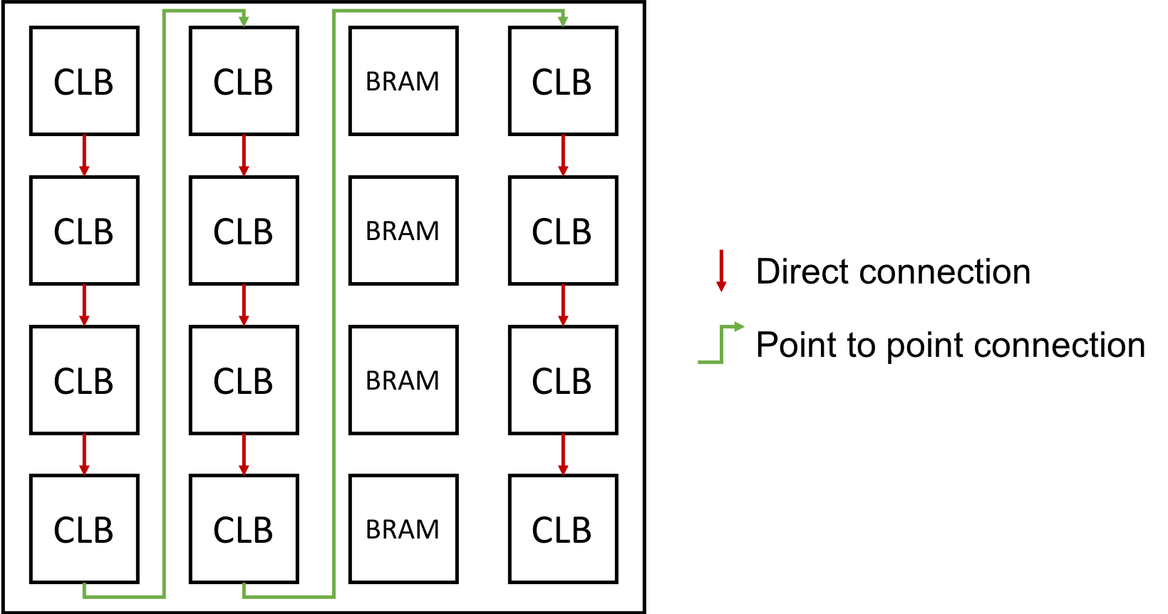
Fig. 34 An example of scan-chain implementation
In this figure, the red arrows represent the initial direct connection. The green arrows represent the point to point connection to connect all the columns of CLB.
A point to point connection can be applied in different ways than showed in the example section. To help the designer implement his point to point connection, a truth table with our new parameters id provided below.
Fig. 35 provides all possible variable combination and the connection it will generate.
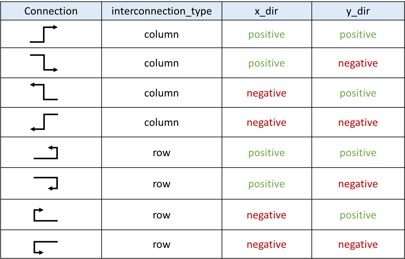
Fig. 35 Point to point truth table