Simulation settings
All the simulation settings are stored under the XML node <openfpga_simulation_setting>
General organization is as follows
<openfpga_simulation_setting>
  <clock_setting>
    <operating frequency="<int>|<string>" num_cycles="<int>|<string>" slack="<float>">
      <clock name="<string>" port="<string>" frequency="<float>"/>
      ...
    </operating>
    <programming frequency="<int>">
      <clock name="<string>" port="<string>" frequency="auto|<float>" is_shift_register="<bool>"/>
      ...
    </programming>
  </clock_setting>
  <simulator_option>
    <operating_condition temperature="<int>"/>
    <output_log verbose="<bool>" captab="<bool>"/>
    <accuracy type="<string>" value="<float>"/>
    <runtime fast_simulation="<bool>"/>
  </simulator_option>
  <monte_carlo num_simulation_points="<int>"/>
  <measurement_setting>
    <slew>
      <rise upper_thres_pct="<float>" lower_thres_pct="<float>"/>
      <fall upper_thres_pct="<float>" lower_thres_pct="<float>"/>
    </slew>
    <delay>
      <rise input_thres_pct="<float>" output_thres_pct="<float>"/>
      <fall input_thres_pct="<float>" output_thres_pct="<float>"/>
    </delay>
  </measurement_setting>
  <stimulus>
    <clock>
      <rise slew_type="<string>" slew_time="<float>"/>
      <fall slew_type="<string>" slew_time="<float>"/>
    </clock>
    <input>
      <rise slew_type="<string>" slew_time="<float>"/>
      <fall slew_type="<string>" slew_time="<float>"/>
    </input>
  </stimulus>
</openfpga_simulation_setting>
Clock Setting
Clock setting focuses on defining the clock periods to applied on FPGA fabrics As a programmable device, an FPGA has two types of clocks. The first is the operating clock, which is applied by users’ implementations. The second is the programming clock, which is applied on the configuration protocol to load users’ implementation to FPGA fabric. OpenFPGA allows users to freely define these clocks as well as the number of clock cycles. We should the full syntax in the code block below and then provide details on each of them.
<clock_setting>
  <operating frequency="<float>|<string>" num_cycles="<int>|<string>" slack="<float>">
    <clock name="<string>" port="<string>" frequency="<float>"/>
    ...
  </operating>
  <programming frequency="<float>">
    <clock name="<string>" port="<string>" frequency="auto|<float>" is_shift_register="<bool>"/>
    ...
  </programming>
</clock_setting>
Operating clock setting
Operating clocks are defined under the XML node <operating>
To support FPGA fabrics with multiple clocks, OpenFPGA allows users to define a default operating clock frequency as well as a set of clock ports using different frequencies.
- <operating frequency="<float>|<string>" num_cycles="<int>|<string>" slack="<float>"/>
frequency="<float|string>Specify frequency of the operating clock. OpenFPGA allows users to specify an absolute value in the unit of[Hz]Alternatively, users can bind the frequency to the maximum clock frequency analyzed by VPR STA engine. This is very useful to validate the maximum operating frequency for users’ implementations In such case, the value of this attribute should be a reserved wordauto.
Note
The frequency is considered as a default operating clock frequency, which will be used when a clock pin of a multi-clock FPGA fabric lacks explicit clock definition.
num_cycles="<int>|<string>"can be eitherautoor an integer. When set toauto, OpenFPGA will infer the number of clock cycles from the average/median of all the signal activities. When set to an integer, OpenFPGA will use the given number of clock cycles in HDL and SPICE simulations.slack="<float>"add a margin to the critical path delay in the HDL and SPICE simulations. This parameter is applied to the critical path delay provided by VPR STA engine. So it is only valid when optionfrequencyis set toauto. This aims to compensate any inaccuracy in STA results. Typically, the slack value is between0and1. For example,slack=0.2implies that the actual clock period in simulations is 120% of the critical path delay reported by VPR.
Note
Only valid when option frequency is set to auto
Warning
Avoid to use a negative slack! This may cause your simulation to fail!
- <clock name="<string>" port="<string>" frequency="<float>"/>
name="<string>Specify a unique name for a clock signal. The name will be used in generating clock stimulus in testbenches.port="<string>Specify the clock port which the clock signal should be applied to. The clock port must be a valid clock port defined in OpenFPGA architecture description. Explicit index is required, e.g.,clk[1:1]. Otherwise, default index0will be considered, e.g.,clkwill be translated asclk[0:0].
Note
You can define clock ports either through the tile annotation in Physical Tile Annotation or Circuit Port.
frequency="<float>Specify frequency of a clock signal in the unit of[Hz]
Warning
Currently, we only allow operating clocks to be overwritten!!!
Programming clock setting
Programming clocks are defined under the XML node <programming>
- <programming frequency="<float>"/>
frequency="<float>"Specify the frequency of the programming clock using an absolute value in the unit of[Hz]This frequency is used in testbenches for programming phase simulation.
- <clock name="<string>" port="<string>" frequency="auto|<float>" is_shift_register="<bool>"/>
name="<string>Specify a unique name for a clock signal. The name should match a reserved word of programming clock, i.e.,bl_sr_clockandwl_sr_clock.Note
The
bl_sr_clockrepresents the clock signal driving the BL shift register chains, while thewl_sr_clockrepresents the clock signal driving the WL shift register chainsport="<string>Specify the clock port which the clock signal should be applied to. The clock port must be a valid clock port defined in OpenFPGA architecture description. Explicit index is required, e.g.,clk[1:1]. Otherwise, default index0will be considered, e.g.,clkwill be translated asclk[0:0].frequency="auto|<float>Specify frequency of a clock signal in the unit of[Hz]. Ifautois used, the programming clock frequency will be inferred by OpenFPGA.is_shift_register="<bool>Specify if this clock signal is used to drive shift register chains in BL/WL protocols
Note
Programming clock frequency is typically much slower than the operating clock and strongly depends on the process technology. Suggest to characterize the speed of your configuration protocols before specifying a value!
Simulator Option
This XML node includes universal options available in both HDL and SPICE simulators.
Note
This is mainly used by FPGA-SPICE
Operating condition
- <operating_condition temperature="<int>"/>``
temperature="<int>"Specify the temperature which will be defined in SPICE netlists. In the top SPICE netlists, it will show as
.temp <int>
Output logs
- <output_log verbose="<bool>" captab="<bool>"/>``
Specify the options in outputting simulation results to log files
verbose="true|false"Specify if the simulation waveforms should be printed out after SPICE simulations. If turned on, it will show in all the SPICE netlists
.option POST
Note
when the SPICE netlists are large or a long simulation duration is defined, the post option is recommended to be off. If not, huge disk space will be occupied by the waveform files.
captab="true|false"Specify if the capacitances of all the nodes in the SPICE netlists will be printed out. If turned on, it will show in the top-level SPICE netlists
.option CAPTAB
Note
When turned on, the SPICE simulation runtime may increase.
Simulation Accuracy
- <accuracy type="<string>" value="<float>"/>``
Specify the simulation steps (accuracy) to be used
type="abs|frac"Specify the type of transient step in SPICE simulation.
When
absis selected, the accuracy should be the absolute value, such as1e-12.When
fracis selected, the accuracy is the number of simulation points in a clock cycle period, for example, 100.
value="<float>"Specify the transient step in SPICE simulation. Typically, the smaller the step is, the higher the accuracy that can be reached while the long simulation runtime is. The recommended accuracy is between 0.1ps and 0.01ps, which generates good accuracy and runtime is not significantly long.
Simulation Speed
- <runtime fast_simulation="<bool>"/>
Specify if any runtime optimization will be applied to the simulator.
fast_simulation="true|false"Specify if fast simulation is turned on for the simulator.
If turned on, it will show in the top-level SPICE netlists
.option fast
Monte Carlo Simulation
- <monte_carlo num_simulation_points="<int>"/>
Run SPICE simulations in monte carlo mode. This is mainly for FPGA-SPICE When turned on, FPGA-SPICE will apply the device variation defined in Technology library to monte carlo simulation
num_simulation_points="<int>"Specify the number of simulation points to be considered in monte carlo. The larger the number is, the longer simulation time will be but more accurate the results will be.
Measurement Setting
Users can define the parameters in measuring the slew of signals, under XML node
<slew>Users can define the parameters in measuring the delay of signals, under XML node
<delay>
Both delay and slew measurement share the same syntax in defining the upper and lower voltage thresholds.
- <rise|fall upper_thres_pct="<float>" lower_thres_pct="<float>"/>
Define the starting and ending point in measuring the slew of a rising or a falling edge of a signal.
upper_thres_pct="<float>"the ending point in measuring the slew of a rising edge. It is expressed as a percentage of the maximum voltage of a signal. For example, the meaning of upper_thres_pct=0.95 is depicted in Fig. 36.lower_thres_pct="<float>"the starting point in measuring the slew of a rising edge. It is expressed as a percentage of the maximum voltage of a signal. For example, the meaning of lower_thres_pct=0.05 is depicted in Fig. 36.
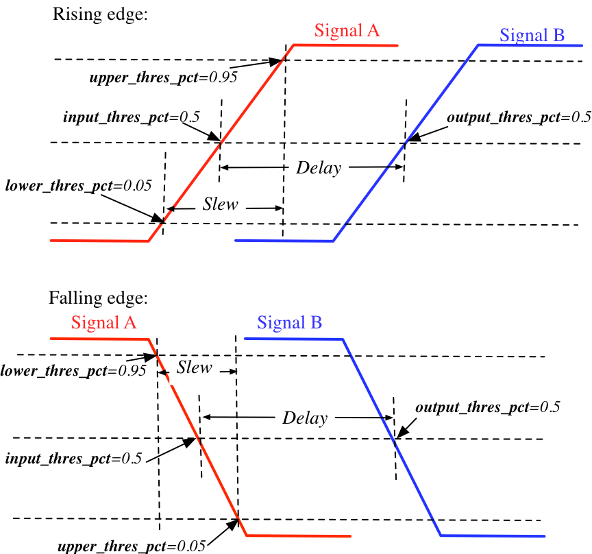
Fig. 36 An illustrative example on measuring the slew and delay of signals
Stimulus Setting
Users can define the slew time of input and clock signals to be applied to FPGA I/Os in testbenches under XML node <clock> and <input> respectively.
This is used by FPGA-SPICE in generating testbenches
- <rise|fall slew_type="<string>" slew_time="<float>"/>
Specify the slew rate of an input or clock signal at rising or falling edge
slew_type="[abs|frac]"specify the type of slew time definition at the rising or falling edge of a lock/input port.The type of
absimplies that the slew time is the absolute value. For example,slew_type="abs" slew_time="20e-12"means that the slew of a clock signal is 20ps.The type of
fracmeans that the slew time is related to the period (frequency) of the clock signal. For example,slew_type="frac" slew_time="0.05"means that the slew of a clock signal takes 5% of the period of the clock.
slew_time="<float>"specify the slew rate of an input or clock signal at the rising/falling edge.
Fig. 36 depicts the definition of the slew and delays of signals and the parameters that can be supported by FPGA-SPICE.